Summary
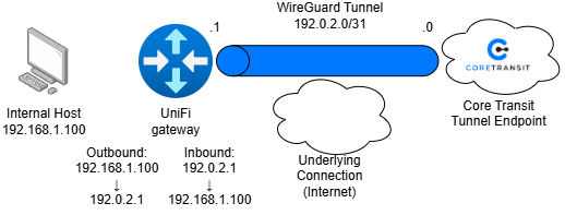
Below is an example of how to implement a Destination NAT rule and Source NAT masquerade configuration on a UniFi Gateway. The configuration allows inbound traffic from the public internet to reach an internal host while ensuring outbound traffic is translated to the gateway’s public IP address.
The purpose of this configuration is to publish internal services to the internet while maintaining private addressing on the LAN.
Use Cases
- Web server hosting – forward TCP 80 and TCP 443 to an internal web server
- Remote Desktop – Forward TCP 3389 to a workstation
- CCTV Access – Forward vendor-specific ports to surveillance equipment
Diagram
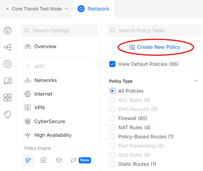
Finding the Policy Table
In the UniFi Site Manager, find the "Control Plane" button for the node you wish to configure.
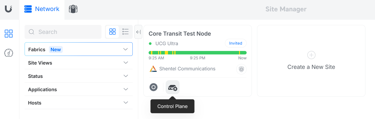
Once in the Control Plane, under the "Policy Engine" section, find the button labeled "Policy Table".
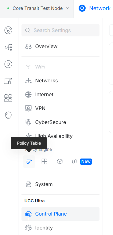
After entering the policy table, find the option to "Create New Policy".
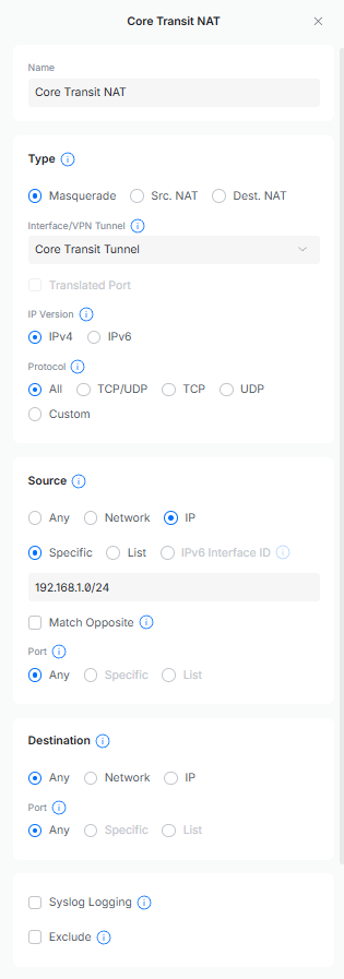
Source NAT (Masquerade)
Allows internal devices using private IP addresses to communicate with the internet.
Traffic Flow:
Source: 192.168.1.x/24 (all internal traffic to the internet)
Translated to: 192.0.2.1
The NAT Masquerade policy should look something like this:
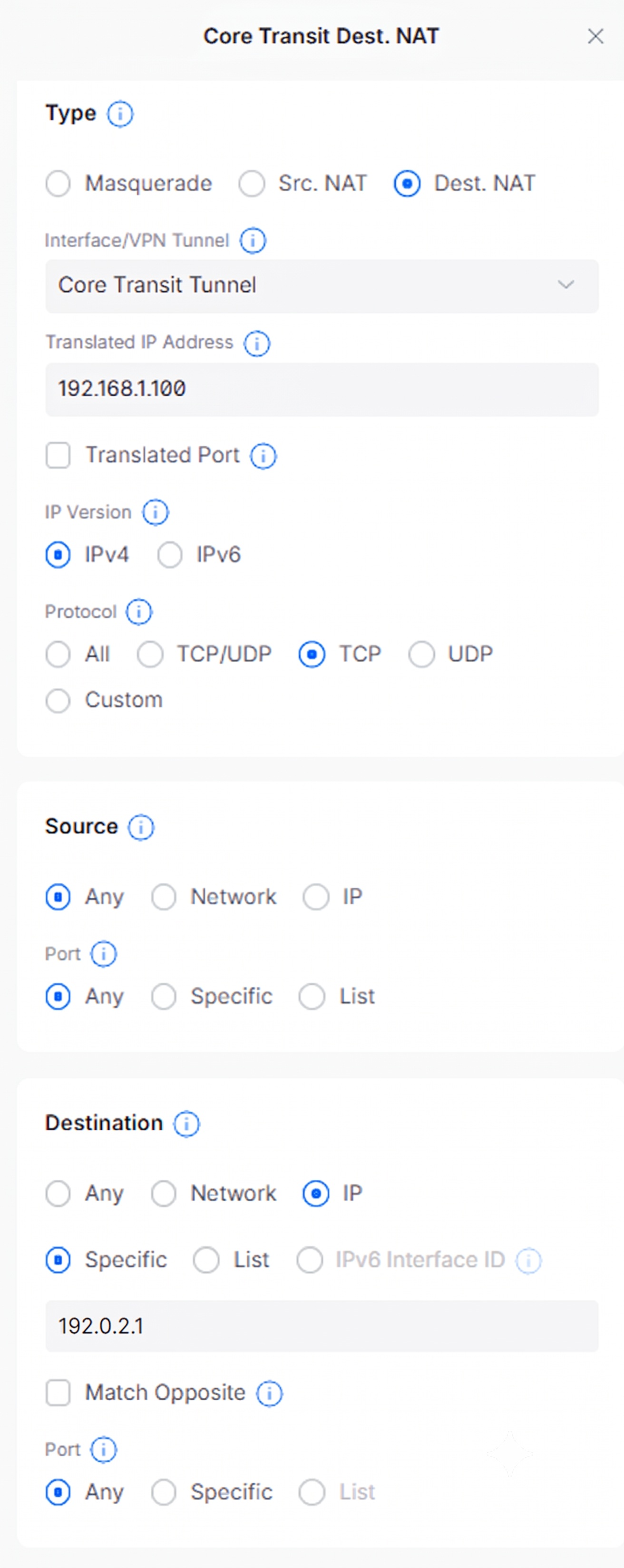
Destination NAT (Port Forward)
Allows inbound internet traffic to reach an internal device that's hosting a service or application.
Traffic Flow:
Source: 192.0.2.1
Translated to: 192.168.1.100
The Destination NAT policy should look something like this:
For security, it is recommended to create a firewall policy that whitelists only the necessary ports.
The IP address used in the “Destination” section should be the IP address assigned to the core transit tunnel endpoint you are facing.
Packet Flow Breakdown
Inbound Traffic:
- Internet client connects to the public IP address
- UniFi receives the packet on the Core Transit tunnel interface.
- Destination NAT rule matches.
- Destination IP address is rewritten to the internal host.
- Packet is forwarded to the LAN.
Outbound Traffic:
- Internal host initiates a connection.
- Packet exits the LAN.
- Masquerade rule matches.
- Source IP address is rewritten to the public IP of the Core Transit Tunnel.
- Traffic is forwarded to the internet.
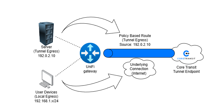
Policy Based Routing
Option 1: Policy-Based Routing Using a Single Host
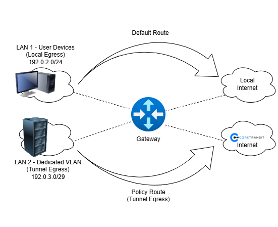
Policy-Based Routing (PBR) allows specific devices to use a designated network path while all other devices continue using the default Internet connection. In this deployment, a UniFi gateway routes traffic from a specific host (for example, web server or application server) through a Core Transit WireGuard tunnel while all other LAN devices continue to use the customer's ISP connection.
The policy route matches traffic based on the source IP address of the target device. Traffic originating from the specified host is forwarded through the Core Transit tunnel, while traffic from all other devices follows the standard WAN route.
This design is ideal for testing, proof-of-concept deployments, or environments where only a single server requires access to Core Transit services.
Use Cases
- Testing Core Transit connectivity before a larger deployment.
- Hosting a single web server using Core Transit public IP space.
- Routing a single application server through Core Transit.
- Migrating services to Core Transit without affecting the rest of the network.
- Development or lab environments.
Advantages
- Simple to configure.
- No VLAN changes required.
- Minimal impact on existing network design.
- Fast troubleshooting and validation.
Limitations
- Each server requires its own policy route.
- Does not scale well for multiple servers.
- More administrative overhead as the environment grows.
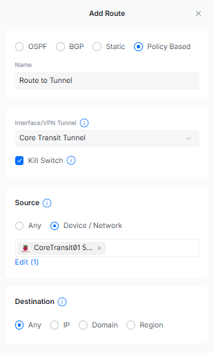
Diagram
In the Control Plane, within the Policy Engine section, find the Routing Table. Click on “Create New Route”, select “Policy Based”. Then select the Core Transit Tunnel as the interface and find the MAC address of the node that will be routed through the tunnel.
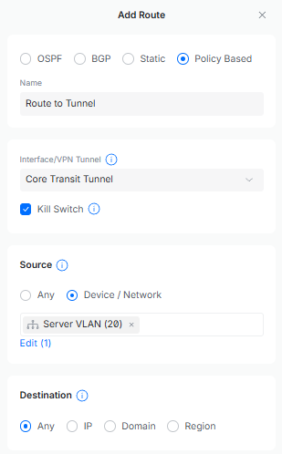
Option 2: Policy-Based Routing Using a Dedicated VLAN
Policy-Based Routing can be combined with VLAN segmentation to direct an entire group of devices through a Core Transit tunnel. In this design, servers are placed into a dedicated VLAN and a policy route is created to send all traffic originating from that VLAN through the Core Transit WireGuard tunnel.
User devices, printers, phones, and other business systems remain on the default network and continue to use the customer's ISP connection. Only devices located within the Server VLAN are routed through Core Transit.
This approach provides a scalable and repeatable architecture for organizations hosting multiple public-facing services while maintaining separation between production servers and end-user devices.
Use Cases
- Small business server networks.
- Multiple web servers or application servers.
- Hosting services with Core Transit public IP addresses.
- Customer environments requiring separation between users and servers.
- Managed service provider deployments.
Advantages
- Highly scalable.
- Easier long-term management.
- Better security through segmentation.
- Simplified policy management.
- Consistent routing behavior for all servers.
Limitations
- Requires VLAN-capable networking equipment.
- More complex initial deployment.
- Requires switch port configuration and VLAN planning.
Diagram
Find the “Networks” section at the top of the Control Plane. Then click on “Create New” to create the dedicated VLAN. Once the VLAN has been created and assigned a port, go to the Routing Table in the Policy Engine. Click on “Create New Route” and select “Policy Based”. Choose the Core Transit Tunnel as the interface and select the dedicated VLAN as the Device/Network.