Summary
Below is an example of how to implement a Destination NAT rule and Source NAT masquerade configuration on a UniFi Gateway. The configuration allows inbound traffic from the public internet to reach an internal host while ensuring outbound traffic is translated to the gateway’s public IP address.
The purpose of this configuration is to publish internal services to the internet while maintaining private addressing on the LAN.
Use Cases
Web server hosting – forward TCP 80 and TCP 443 to an internal web server
Remote Desktop – Forward TCP 3389 to a workstation
CCTV Access – Forward vendor-specific ports to surveillance equipment
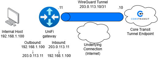
Diagram
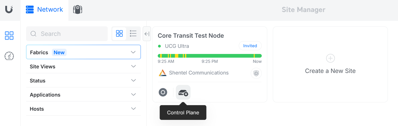
Finding the Policy Table
In the UniFi Site Manager, find the "Control Plane" button for the node you wish to configure.
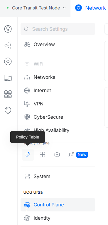
Once in the Control Plane, under the "Policy Engine" section, find the button labeled "Policy Table".
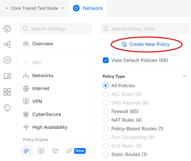
After entering the policy table, find the option to "Create New Policy".
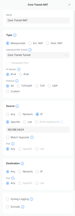
Source NAT (Masquerade)
Allows internal devices using private IP addresses to communicate with the internet.
Traffic Flow:
Source: 192.168.1.x/24 (all internal traffic to the internet)
Translated to: 203.0.113.10
The NAT Masquerade policy should look something like this:
Destination NAT (Port Forward)
Allows inbound internet traffic to reach an internal device that's hosting a service or application.
Traffic Flow:
Source: 203.0.113.10
Translated to: 192.168.1.100
The Destination NAT policy should look something like this:

In the “Source” section under “Port”, it is recommended to only list necessary ports. A firewall policy may need to be added to whitelist these ports.
The IP address used in the “Destination” section should be the IP address assigned to the core transit tunnel endpoint you are facing.
Packet Flow Breakdown
Inbound Traffic:
- Internet client connects to the public IP address
- UniFi receives the packet on the Core Transit tunnel interface.
- Destination NAT rule matches.
- Destination IP address is rewritten to the internal host.
- Packet is forwarded to the LAN.
Outbound Traffic:
- Internal host initiates a connection.
- Packet exits the LAN.
- Masquerade rule matches.
- Source IP address is rewritten to the public IP of the Core Transit Tunnel.
- Traffic is forwarded to the internet.
This document uses RFC 5737 documentation addresses. These addresses are reserved for examples and documentation and should not be used on production networks.


